Vacuum sewerage system – FLOVAC
Differential air pressure is the driving force in Flovac vacuum sewer systems
Flovac vacuum sewerage system
The pressure differential between the atmospheric pressure and the vacuum in the sewer lines of 50kPa – 70kPa provides the energy required to open the FloVac valves and to transport the sewage.
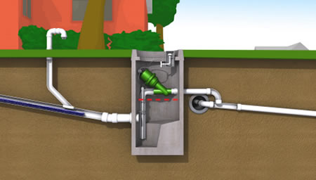
Sewage flows by gravity from homes into a collection chamber. When 40 litres accumulates in the sump, the vacuum interface valve located above the sump automatically opens and differential air pressure propels the sewage through the valve and into the vacuum main.Sewage flows through the vacuum lines and into the collection tank at the vacuum station. Sewage pumps transfer the sewage from the collection tank to the wastewater treatment facility or nearby gravity manhole. There are no electrical connections required at the home. Power is necessary only at the vacuum station.

As no sewage is sitting anywhere in the network for any length of time it is obvious that no septicity can occur and therefore no odours.
The Collection chamber

Collection chambers can be made out of a variety of materials, most commonly, concrete, PE, Fibreglass, or even stainless steel. Flovac will supply a pit fully fitted out to meet local conditions.
Most operators and installer prefer the new FLOVAC PE chamber which comes fully fitted with the Flovac valve and all fittings. As it is lightweight, installation is easier as is transportation. Operators prefer the new Flovac chamber as the valve is located in a separate section ensuring that they come into no contact with the sewage at any point. This partitioning of the chamber also ensures that stormwater cannot enter the system via the lid of the chamber. (Ask your Flovac representative for details)
Advanced monitoring at the collection pit can notify the operator and asset owner of a wealth of information about the system:
- Number of valve firings
- Information about Illegal connection of stormwater pipes or broken gravity lines with the property boundary
- Information on wear and tear on valve parts
- Operator warning of a problem with the valve
The Flovac Valve
The FLOVAC Valve is the latest in the evolution of the vacuum interface valve. Fully complying with EN1091 and with The Australian Standard AS 4310. The changes that have been made have come from not only our own operational experience with input from a number of experts around the world.
Features and Benefits
- 78 mm + internal diameter. More than 5 % greater flow area than competition’s 3” valve, yet fits with standard 90 mm or 3”pipe.
- Superior Cv – Better through flow allowing less friction loss and more efficient systems.
- Colour coordinated tubing and tubing connections – provides correct assembly in the field by unskilled labour.
- Lower housing spigots with hose barbs – maintains tight, correct fit of tubing, eliminating hose disconnects and valve failure.
- Superior fusion welded, large threaded insert ring on wye body.
- Twice as strong as the competition. Not affected by severe water hammer. Standard rebuild components, compatible with existing systems parts.
- Revolutionary “Easy Clip” system to retain controller properly on valve. Positions and holds controller in only correct position and maintains vacuum seal between valve and controller. Eliminates vacuum leaks

FLOVAC Controller
Features and Benefits
- Unique 3 bolt design allows more uniform assembly tension of body parts and ease of assembly.
- Simplified “one way” assembly pins allowing only correct assembly of main body components. Virtually eliminates improper assembly of main controller parts.
- Superior foot design creates less vacuum leaks.
- Utilizes revolutionary “Easy Clip” mounting clip, causing correct location of controller to the valve with simple on/off assembly.
- Colour coordinated spigots aiding in easy and correct installation of tubing.
Flovac vacuum mains

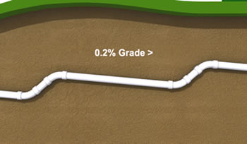
Vacuum mains are of a smaller diameter than gravity mains for a given flow because they are designed to operate with higher velocities and under two phase flow conditions, this provides for more efficient fluid transport and also maintains the pipe in a much cleaner condition than gravity. The vacuum mains are PE PN 10 or PVC Class 9 or Class 12.
The size of the vacuum mains, the shallow depth of construction and the speed at which installation occurs all reduces our impact on the environment and reduces our carbon footprint. If a break ever occurred in a vacuum main, no contamination occurs as the negative pressure does not allow any sewage to leak into the environment. A break will also be quickly alerted to the operators as the vacuum pumps running time will increase. Residents will not be inconvenienced as a rare break is easy to find and repair. If our pipework was 5-10 metres deep as with a gravity sewer this would be far more difficult.
Gone are the days when operators need to enter the sewer pipes or worry about gas buildups or rats or snakes in the system.
Flovac Vacuum Pump Station

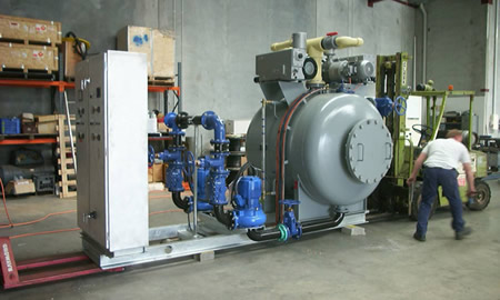
Vacuum pumps typically run 2 to 3 hours each per day depending on the design approach and don’t need to run continuously since the vacuum interface valves are normally closed. As sewage enters the system, driven by air at atmospheric pressure, the system vacuum will slowly decrease from -70kPa to -50kPa. The vacuum pumps are sized to increase the system vacuum from -50kPa to -70kPa in three minutes or so. The two non-clog sewage pumps are each sized for peak flow. Energy consumption can be calculated at the design phase for a particular project.
The collection tank is usually mild steel or stainless steel and is sized according to flow with typical sizes ranging from 3.8 to 15 cubic meters. The incoming vacuum lines connect individually to the collection tank, effectively dividing the system into zones.
Monitoring at the pump station can alert operators to a number of things:
- Long pump hours or a low vacuum alarm suggesting a blockage in a vacuum valve in the reticulation or a break in the vacuum main.
- High alarms for the tank to notify of problems with the discharge pumps.
- Pump faults calling for service to vacuum or sewage pumps.
- Information for asset owners about pump efficiencies as well as air/liquid ratios to assist with power saving.
- The pump station building can vary considerably depending on the type of project. It can be designed to fit in with other houses in the areas or if in an industrial area could be placed inside a container. In some projects the pump station has been put completely underground.